

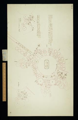
Gearings, et cetera of Sketch No. 8 dated July 31 1835. Arrangement.
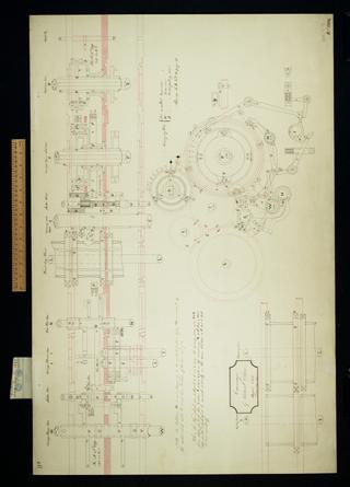
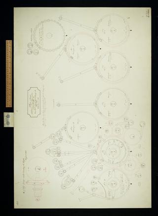
Carriage by vertical chain. Plan, elevation.

This plan is entitled 'Carriage 9. Gearing et cetera of Sketch No. 8'

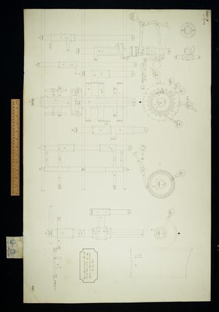
Lifters for selecting the multiple of the Multiplicand or Divisor. Plan, two elevations.

Sketch of wheels for reducing carrying figure wheel axes to zero and setting spiral axes. Sketch elevations.

Figure 1. Clutch et cetera for driving the adding axes. Plan, elevation.

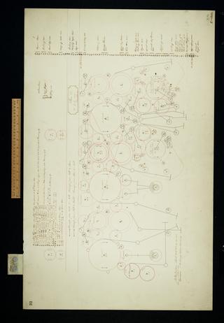
Sketches of mill used for arranging operations on the engine of four wheels in each cage from April 1836 - August 1837.

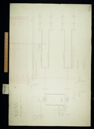
Plan and section of an 8 inch figure wheel; hoarding carriage and framing plate. Plan, elevation.
Consecutive counting apparatus.

Carriage and method of setting spiral axes for a machine of 50 cages with two figure wheels in each cage. Plan, elevation, details.

Method of governing barrels et cetera. No. 1, plan of elevation.

Combinatorial and decimal counting apparatus comprising plan, elevation and description.

Centres of axes and pen sketches of lockings for Sketch 14. Arrangement.

Sketch of central wheel and principal framing. Plan, elevation.

Multiplication before the invention of multiplication by table. Sheet 1 of 2.
Multiplication before the invention of multiplication by table. Sheet 2 of 2.

Method of bolting to platforms for vertical motion of axes, plan.

Sketch No. 11, circular, arrangement. Shows 27 variables.

Notation of units

Figure 1. First method of stepping by long pinions, elevation.

Sketch 12. Stepping by the method designed 15 April 1836. Circular arrangement, 27 variables.

Sketch of sectors for lifting the axes.

Sketch of some of the centres et cetera for Plan 16. Arrangement.

Plan 16. Arrangement, several partial arrangements, numerous notes.

Sketch of sectors for giving vertical motion to axes. Arrangement, design, sketch for interference.

Notation of units

Sketch of a decimal counting apparatus. Plan, elevation, description.
Plan 27. Linear arrangement with letter notations.
Plan No. 24. Arrangement and rack, rearrangement or notes.

Locking motions for carriage column.
Elevation of arrangement 13 with some of the driving and directive. Elevation includes section of a barrel '65 bands 80 verticals'.

General Plan No. 23. Arrangement and rack.

Figure 1, Plan / Figure 2, elevation, Figure C Carriage No 4.

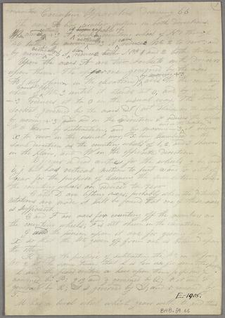
Plan of an improved carriage by vertical chain, and a page of handwritten notes

Adding No. 6, carrying No. 14. Sketch of a method of adding and carrying intended for a Difference machine. Designed between 31 October 1836 and 12 November 1836. Plan, elevations, details, description.
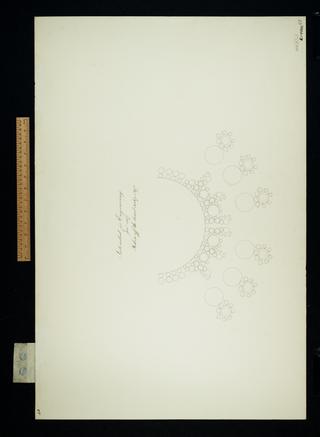
Intended for engraving. Shows six barrels with reducing apparatus.

Plan of the left half to middle group for General Plan 28.
Sign apparatus for Plan 28a. Plan, elevation.
Plan of consecutive mill counting apparatus for General Plan 28. Plan, note.

Plan and elevation for the calculating part of the Difference Engine. Figure 1. Superseded. Consecutive carriage.

Sketch of an apparatus for advancing stereotype frames of the Difference Engine by cranks and backing them by weights. Superseded. Plan, elevation.

Axes D1 E1 for the left hand group of Plan 28. Plan, elevation.

Plan titled, 'Various arrangements proposed, examined and rejected between the rejection of Plan 27 and the adoption of Plan 28. Figures 1, 2, 3, 4, 9. Various', and a folded sheet of notes

First sketch of all the parts in plan of the right half to middle group of General Plan 28. Plan, elevation.

Sundry axes and wheels for Plan 28.

Speculations on the driving and directive for the Difference Engine. Superseded. Arrangements.

Improved framing for centre group of Plan 28. Arrangement, plan.

Difference Engine wheels for driving the cranks which move the matrix frames. Superseded. Plan, elevation.
